| Engine cooling | ||
|
Chassis |
Cooling and coolant circuit
The die-cast aluminum coolant pump is located on the right at the front of the crankcase, and takes the form of a double spiral pump.
The spiral port layout was chosen so that the volumetric flow is evenly distributed between the right and left banks without having to resort to restriction measures that would be detrimental to efficiency.
The coolant is pumped into the two cylinder banks of the crankcase from the front via the two spiral ports. From there it is directed by corresponding bores in the cylinder head gasket and flows into the cylinder heads primarily through the exhaust side. The cylinder heads are cooled by a cross-flow principle.
Through coolant rails located on the intake side on the inside of the V, the coolant is directed to the thermostat housing where it is split into a bypass stream and a cooling stream. The control temperature of the coolant thermostat at the outlet end is 87 °C. In model 211 the thermostat is electrically heated.
The cooling stream for the oil/water heat exchanger is taken from the right side of the crankcase. The EGR cooler and heater heat exchanger are supplied from the coolant rail in the left-hand cylinder head.
Overall the coolant circuit is designed so as to guarantee adequate heat dissipation under all load and rpm conditions.
High flow rates and good heat transfer are achieved especially in the following areas:
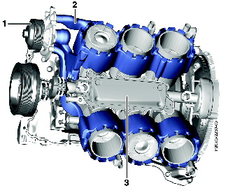
Cooling
1 Coolant pump
2 Water jacket
3 Oil/water heat exchanger