| Subsystems - Exhaust System | ||
| Combustion |
Overview
Catalytic converter system
The exhaust system in model series 211 complies with emissions standard BIN 8 and consists of:
- Oxidation catalytic converter
- Oxygen sensor upstream and downstream of NOX storage catalytic converter
- NOX storage catalytic converter
- Temperature sensor in catalytic converter
- Temperature sensor upstream of DPF
- Diesel particulate filter with pressure differential sensor
- Odor filter
The exhaust system in model series 164 and 251 complies with emissions standard BIN 10 and consists of:
- Oxygen sensor upstream of catalytic converter
- Oxidation catalytic converter
- Temperature sensor in catalytic converter
- Temperature sensor upstream of DPF
- Diesel particulate filter with pressure differential sensor
The oxidation catalytic converters are based on a cordierite substrate and are coated with a material containing rare metals (platinum).
Diesel particulate filter
The diesel particulate filter consists of silicon carbide and can reach separation rates in excess of 99 % based on the particulate mass it filters from the exhaust gas. The soot particles (carbon particles) deposited on the walls of the filter are oxidized at exhaust gas temperatures above approx. 600 °C to form carbon dioxide (CO2). These exhaust gas temperatures, which are necessary for regeneration of the diesel particulate filter, can be achieved randomly via the load spectrum or specifically via a secondary fuel injection. The engine control initiates the filter regeneration based on the pressure and temperature of the exhaust gas in the diesel particulate filter.
BlueTech
This year will see the introduction of a new technology to reduce nitrogen oxides (denoxing).
This technology is called BLUETEC and is installed for the first time in model series 211.
In addition to an oxidation catalytic converter and diesel particulate filter, the BLUETEC system employs an NOX storage catalytic converter and an odor filter.
The NOXstorage catalyst stores the nitrogen oxides in partial-load operation. During short regeneration phases with rich air/fuel ratios, it converts them into harmless nitrogen.
Exhaust Gas Recirculation (EGR)
The use of EGR can reduce NOX emissions up to a certain degree without increasing particle emissions. The accumulator injection system, the common rail, has a positive effect on the EGR mode.
With exhaust gas recirculation, a part of the exhaust gas under partial-load conditions is taken from the exhaust manifold and directed through the exhaust gas recirculation cooler and the exhaust gas recirculation positioner into the intake manifold.
This reduces various important values:
- Oxygen level
- Combustion rate
- Peak temperature at the ignition flame-front (and thereby NOX emissions)
However, if the recirculated exhaust quantity is too high, fuel consumption rises due to lack of oxygen and the following emission levels increase:
EGR is controlled by the CDI control module according to a performance map.
The EGR positioner is actuated by the CDI control module. The CDI control module calculates the air mass on the basis of the input signals of the MAF sensor and regulates the corresponding EGR volume for the applicable operating condition.
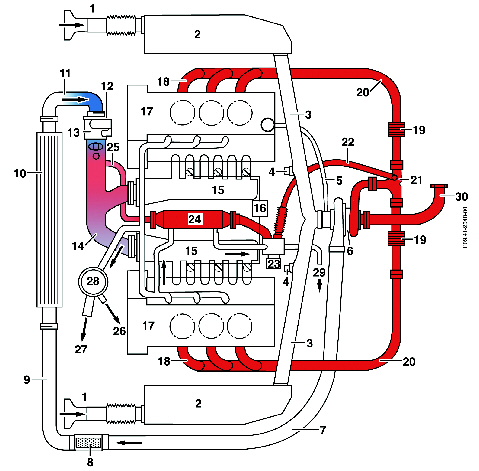
|
4 Left/right hot film mass air flow sensor |
Diesel Particulate Filter Regeneration
The CDI control module initiates DPF regeneration by periodically increasing the exhaust gas temperature to in excess of 550 °C, e.g. the soot particles stored in the DPF are burned to form predominantly CO2. The ash produced remains in the DPF. The temperature sensor upstream of the catalytic converter and the temperature sensor upstream of the DPF monitor the exhaust gas temperature during regeneration. The pressure differential sensor uses the exhaust gas pressure lines upstream and downstream of the DPF to measure the difference in pressure between the exhaust gas upstream and downstream of the diesel particulate filter. The ash and soot load in the diesel particulate filter is detected by way of a performance map on the basis of the difference in pressure and the exhaust gas mass calculated by the CDI control module. If the soot load exceeds a value governed by the performance map, the CDI control module initiates the regeneration phase only if the regeneration conditions are fulfilled.
If the maximum fill level
of the
catalytic converter is reached, and if the engine is in a suitable operating
range, the regeneration phase for the catalytic converter is started.
During exhaust gas reduction conditions (λ< 1), the nitrates and sulfates stored in the catalytic converter are broken down into nitrogen oxides or sulfur oxides and are then reduced to nitrogen, carbon dioxide and water or sulfur dioxide and hydrogen sulfide by the reducing agents present in the enriched exhaust gas such as hydrocarbons, carbon monoxides and hydrogen. This process is called NOX or SOX regeneration. An exhaust temperature of 200 °C - 450 °C is used to regenerate the NOX storage catalytic converter. SOX regeneration is made at temperatures starting at 650 °C in the NOX storage catalytic converter. An oxygen sensor downstream of the catalytic converter measures the concentration of oxygen in the exhaust gases and then indicates when the regeneration process is complete by changing its voltage from lean to enriched (λ - change over).
For the short term enrichment of the exhaust gasses, the efficiency of the engine is intentionally reduced by changing the amount of air and fuel. One way of doing this is by reducing the air mass of the intake air by throttling it. This also reduces the boost pressure. Another way is by increasing the amount of fuel injected using an additional secondary injection and by adjusting the quantity injected, the starting point of injection and the pressure in the rail. Enriched operation is performed with no EGR.
Regeneration times and intervals
The regeneration times are dependent on temperature and decrease significantly as the exhaust gas temperature rises.
- About every 800 - 1,600 km
- About 1 - 2 min. total duration (in single phases with max. 20 secs.)
- Starting at 650 °C in NOX storage catalytic converter
DPF regeneration (λ < 1):
Measures to increase the exhaust temperature for DPF regeneration
- Secondary injection
- Exhaust gas recirculation with intake air throttling in overrun mode
- DPF regeneration glowing
Following the regeneration phase, the CDI control module registers the calculated
differences in pressure and compares this value with a reference value.
From this the CDI control module determines the ash load of the diesel particulate
filter.
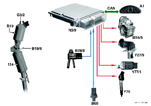
| Exhaust after treatment with DPF (model series 164 and 251 - BIN 10) |
|
|
114 Diesel particulate filter (DPF) B19/9 Temperature sensor upstream of DPF B28/8 Pressure differential sensor (DPF) |
|