| Subsystems - Fuel system | ||
| Combustion |
Overview
The CDI system technology is designed to:
Basic components of the injection system have been revised:
- High pressure pump, max. injection pressure 1600 bar
- Electronic engine control with extended functions for selecting the injection timing point
- Fuel injectors with piezo technology
- Pressure regulator valve
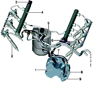
 Fuel feed
 Fuel return
  Injector leak-off fuel/diverted fuel quantity
 High pressure fuel line
Low Pressure System
The fuel supply system provides the injection system with a sufficient quantity of filtered fuel at a sufficient pressure in all operating conditions of the engine.
The fuel pump draws the fuel out of the fuel feed module through a fuel strainer. The housing of the fuel feed module acts as a swirl pot which prevents the fuel pump from drawing in air when the vehicle is cornering or when the fuel level is low.
The electric fuel pump then pumps the drawn-in fuel to the fuel filter (with water level sensor) through the integrated pressure limiting valve. The pressure limiting valve restricts the fuel pressure to approx. 8.5 bar (in case of a blocked line).
The fuel is directed via the fuel filter (with water level sensor) and on to the high pressure pump where it is regulated to approx. 5 bar by the fuel pressure relief valve.
The high pressure pump compresses the fuel to up to 1600 bar (depending on the operating point) and directs it through the two fuel rails to the individual fuel injectors.
The lubricating fuel from the high pressure pump and the diverted fuel from the pressure regulator valve travel through the fuel return line back into the fuel tank. The injector leak-off fuel is fed to the fuel feed inlet via a restrictor.
The returned fuel supplies the suction jet pump, which is located in the bottom of the fuel feed module. In this way the swirl pot (if the fuel tank level is low) is filled with fuel from the fuel tank.
 Injector leak-off fuel/diverted fuel quantity
 High pressure fuel line
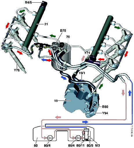
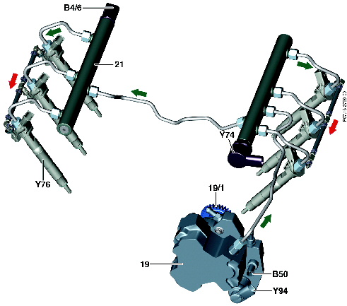
High-Pressure System
The high pressure circuit controls and stores the fuel pressure required for fuel injection. The high pressure pump pumps regulated quantities of fuel into the two rails. The fuel is routed by way of the high pressure lines to the individual fuel injectors.
The CDI control module uses its input signals to detect the current operating condition of the engine and the current requirements of the driver (throttle position).
To adjust the fuel rail pressure, the quantity control valve or the pressure regulator valve, or both, is supplied with a control current according to a performance map until the pressure in the fuel rail reaches the specified pressure. The fuel rail pressure sensor measures the current fuel pressure in the fuel rail and relays a corresponding voltage signal to the CDI control module.
The CDI control module actuates the quantity control valve and pressure regulator valve differently according to the operating condition.
The fuel rail pressure is regulated via the pressure regulator valve under the following conditions:
Pressure differential sensor (BIN 8)
Pressure differential sensor (BIN 10)
The rail pressure is regulated via the quantity control valve under the following conditions:
Pressure differential sensor (BIN 8)
Pressure differential sensor (BIN 10)
Regulation of the rail pressure primarily occurs during quantity control valve operation, except for in the following conditions:
Zero Quantity Calibration
Because of the friction produced when the fuel injectors open and close (due to parts rubbing against one another), the injection duration becomes longer as the parts get older. This is compensated for by the zero quantity calibration. In overrun mode, usually no fuel injection occurs. During the initialization phase of the zero quantity calibration, a constant rail pressure is set by the pressure regulator valve or the quantity control valve. The fuel injectors are then actuated in the overrun mode. The CDI control module then increases the duration of the fuel injection at the injectors. Very small amounts of fuel are injected until an increase in the rpm signal is detected. This new injection duration is compared with the duration of a new fuel injector at a certain calibration amount. The difference is saved as the zero quantity calibration value.